Accelerating Research Equipment Integration with Smart Component Design
Understanding the Integration Landscape
Research equipment integration is the process of connecting disparate scientific instruments, data acquisition modules, and control subsystems so that they function as a cohesive platform. In modern laboratories, a single experiment may involve optical spectrometers, high‑speed cameras, fluidic pumps, and environmental sensors, each originating from different manufacturers and often speaking different communication languages. When these components are not harmonized, researchers encounter fragmented data streams, redundant calibration steps, and increased risk of error. The result is slower time‑to‑insight, higher operational costs, and reduced reproducibility—issues that can jeopardize grant milestones and regulatory compliance.
Key Drivers for Seamless Integration
Three strategic drivers underpin successful research equipment integration: standardization, multi‑domain engineering, and modular connectivity. Each driver addresses a distinct barrier that traditionally slows down the assembly of complex research systems.
Standardization reduces the overhead of translating proprietary data formats into a common language.
Multi‑domain engineering ensures that electrical, optical, thermal, and mechanical considerations are optimized simultaneously, preventing performance bottlenecks.
Modular connectivity enables plug‑and‑play upgrades, extending the lifespan of legacy instruments while adding new capabilities.
Expert Perspective: Industry‑Wide Standards
“Adopting a shared protocol‑template library that defines communication, security, and metadata formats can cut integration time by up to thirty percent while dramatically improving data fidelity across the study lifecycle.” — Elisa Cascade, Senior Director of Clinical Research Operations, Advarra
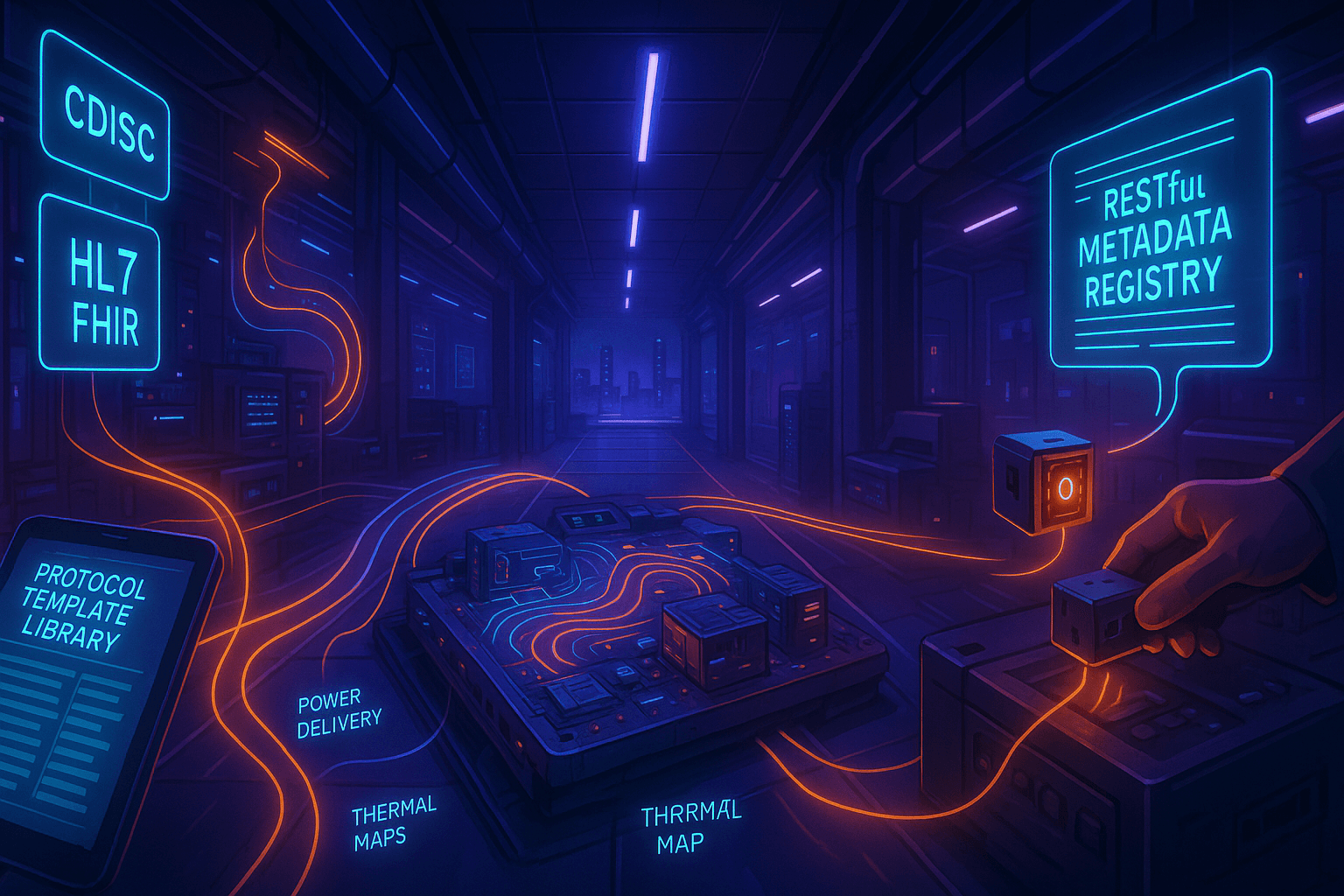
Cascade’s observation highlights the tangible return on investment (ROI) that standardization delivers. When a laboratory adopts universally recognized data exchange standards—such as CDISC for clinical metadata or HL7 FHIR for health‑related measurements—software interfaces can auto‑generate parsers, and validation rules become reusable across projects. This eliminates the need for custom middleware development for every new instrument, allowing research teams to focus on experimental design rather than data plumbing.
Expert Perspective: Heterogeneous Integration Challenges
“Smart component systems require simultaneous optimization across power delivery, signal integrity, EMC, thermal management, and mechanical stress domains. Without standardized multi‑physics simulation workflows, redesign cycles balloon and time‑to‑market suffers.” — European Cooperation for Science and Technology (ECS) Strategic Research and Innovation Agenda
The ECS agenda underscores that modern research platforms are no longer monolithic. A single data‑capture module may contain analog front‑ends, digital signal processors, RF transceivers, and micro‑fluidic channels—all packed into a compact chassis. Engineers must therefore employ multi‑domain simulation tools that can co‑solve electrical, thermal, and mechanical equations. By integrating these tools early in the design phase, teams can predict crosstalk, thermal drift, and mechanical misalignment before hardware is fabricated, reducing costly physical prototyping iterations.
Expert Perspective: Plug‑and‑Play IoT Sensors
“A plug‑and‑play approach using modular sensor nodes that attach to any equipment’s power or data port enables rapid IoT onboarding without custom firmware. Our MQTT + TLS protocol stack, paired with a RESTful metadata registry, provides real‑time monitoring, automated calibration alerts, and centralized analytics.” — Dr. Anika Patel, Head of Product Engineering, Elemental Machines
Patel’s insight demonstrates how modular connectivity translates into operational agility. By standardizing on lightweight, secure messaging (MQTT + TLS) and exposing a RESTful metadata layer, legacy instruments become instantly observable and controllable from a cloud‑based dashboard. Researchers can therefore monitor temperature, vibration, or optical power in real time, receive automated alerts if a parameter drifts out of spec, and trigger corrective actions without manual intervention. The result is a self‑healing laboratory ecosystem that scales with emerging technologies.
Design Framework for Specialized Component Integration
Building on the three expert pillars, a practical design framework can be broken into four stages: discovery, architecture, validation, and deployment. The following table maps typical challenges at each stage to recommended solutions.
Stage | Common Challenge | Strategic Solution |
|---|---|---|
Discovery | Unclear optical, electrical, and environmental requirements across instruments. | Conduct a cross‑functional workshop using a standardized requirements matrix that captures wavelength bands, power budgets, and operating temperature ranges. |
Architecture | Fragmented communication stacks and proprietary connectors. | Adopt a layered architecture: physical layer (fiber or copper), transport layer (Ethernet, CAN, or fiber‑optic protocols), and application layer (FHIR, OPC‑UA, or custom JSON schema). |
Validation | Late‑stage performance surprises such as signal attenuation or thermal runaway. | Run multi‑physics co‑simulation (electrical‑thermal‑mechanical) and perform accelerated life testing on a representative prototype. |
Deployment | Complex commissioning procedures that require manual calibration of each subsystem. | Implement auto‑calibration scripts that read from the RESTful metadata registry and adjust gain, offset, or temperature compensation in real time. |
Best Practices for Implementing Smart Component Design
Leverage a unified data model. Define a canonical schema for all sensor and actuator data. This model becomes the contract between hardware and software, simplifying downstream analytics.
Invest in a modular hardware platform. Use a chassis system that supports interchangeable fiber‑optic, RF, and micro‑fluidic modules. Standardized mounting and connector interfaces accelerate swaps and upgrades.
Integrate security from day one. Enforce TLS encryption on every communication channel and adopt role‑based access control for the metadata registry.
Automate verification. Deploy continuous integration pipelines that run regression tests on simulated data streams whenever a new component version is introduced.
Document the integration workflow. Maintain version‑controlled design files, simulation reports, and test logs in a central repository accessible to all stakeholders.
Measuring Success: Key Performance Indicators
To assess the impact of smart component design on research equipment integration, organizations typically track the following KPIs:
Integration Lead Time: Time from project kickoff to fully operational system.
Data Integrity Rate: Percentage of data packets received without error or loss.
Calibration Cycle Reduction: Decrease in manual calibration hours per month.
System Uptime: Ratio of operational time to scheduled downtime.
Scalability Index: Number of new modules added without requiring architecture redesign.
When the three expert recommendations are applied consistently, many laboratories report a 20‑30 % reduction in integration lead time, a 15 % improvement in data integrity, and a measurable uplift in overall system uptime.
Brand Context: Fiberoptic Systems, Inc. as an Integration Enabler
Fiberoptic Systems, Inc. (FSI) exemplifies the convergence of the three integration pillars. With an in‑house fiber drawing tower, FSI produces custom‑diameter, wavelength‑specific fiber bundles that can be directly interfaced to legacy instrumentation. Their engineering teams apply multi‑domain simulation to ensure that each fiber assembly meets stringent thermal and mechanical tolerances required by aerospace, medical, and defense customers. Moreover, FSI’s modular connector ecosystem embraces industry‑standard protocols, allowing researchers to plug new fiber‑optic channels into existing data acquisition platforms without extensive re‑wiring. By delivering end‑to‑end solutions— from raw preform to field‑ready bundle—FSI reduces the integration burden on research teams, enabling faster experiments and more reliable results.